How Are Components Solded onto a Flexible Printed Circuit Board?
Components Solded onto a Flexible Printed Circuit Board
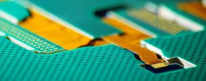
When designing a flexible printed circuit board, designers must balance durability requirements with the need to place components and route traces. Flex circuits typically consist of a thin substrate made from polyimide or polyester-imide material that is etched with copper and covered by a protective layer of dielectric film. They have a high degree of pliability and are highly tolerant to bending. This makes them an ideal choice for many applications, particularly those in which a product must be portable and resilient.
The process of soldering onto a flexible PCB is slightly different from that used for rigid boards. The main difference is that flex circuits must be handled carefully to avoid damage to the material. The temperature profiles used to reflow the solder on rigid PCBs are often too hot for a flexible circuit and can cause blistering or delamination. This means that manufacturers need to be careful when choosing a reflow profile and ensure that the reflow temperature is low enough to prevent this damage.
Another factor that influences durability in a flexible printed circuit board is how the edges of the component are terminated. If they are not treated properly, a flex circuit can tear at the corners or even break in some cases. It is therefore recommended that manufacturers use a tangential corner that has a radius of at least 1.5 mm for the best results. They must also ensure that any through-holes on a flex circuit have the appropriate size to allow for the stress of bending and avoid damage at the solder joint.
How Are Components Solded onto a Flexible Printed Circuit Board?
The way that a flex circuit is fixed to the rigid section before reflow can also affect its durability. If the flex section is made too taut, vibrations in the reflow line can telegraph to the flex portion and cause it to fail as a result of stress. It is therefore important to use the right amount of force to fix the flex section and to ensure that it is held in place with no movement as the board undergoes reflow.
When it comes to ensuring the longevity of a flex circuit, it is essential that designers take the time to design the circuit for maximum reliability. This can be done by using a CAD tool to define regions where the circuit will not bend and making sure that these areas are clearly labeled. In addition, the CAD tool should be used to mark the locations of the vias on the circuit and avoid placing them in areas where they will be subjected to extreme stresses.
In addition, the etching and copper plating processes must be carefully controlled to reduce damage caused by heat. This is because flex circuits are more sensitive to thermal shocks than rigid boards and should be protected from the effects of heat exposure as much as possible. In addition, manufacturers should use a low-melting solder paste to avoid stressing the joints by applying too much heat and should use a suitable cleaning agent to remove any residues after the assembly is complete.